Simple and precise TCP measurement for robots
software development, and cutting technology,
we provide ideal industrial solutions.
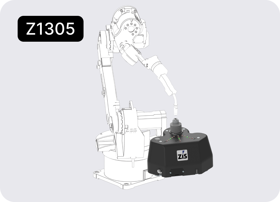
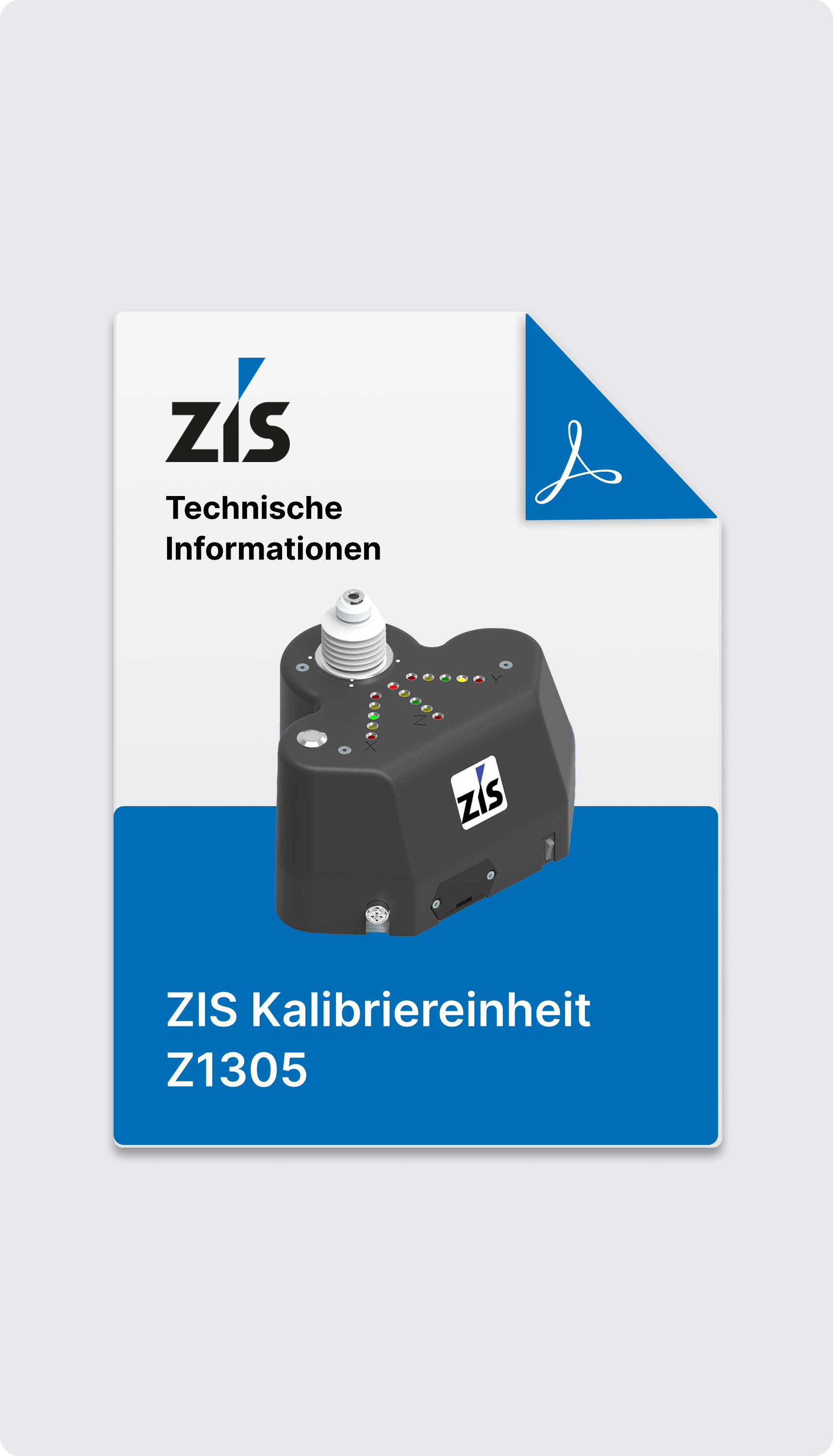
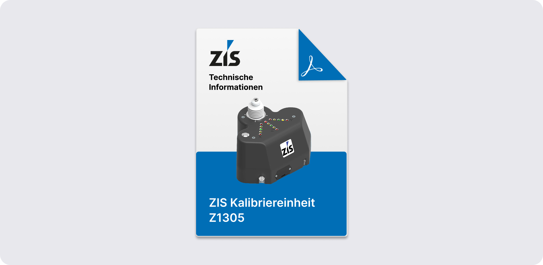
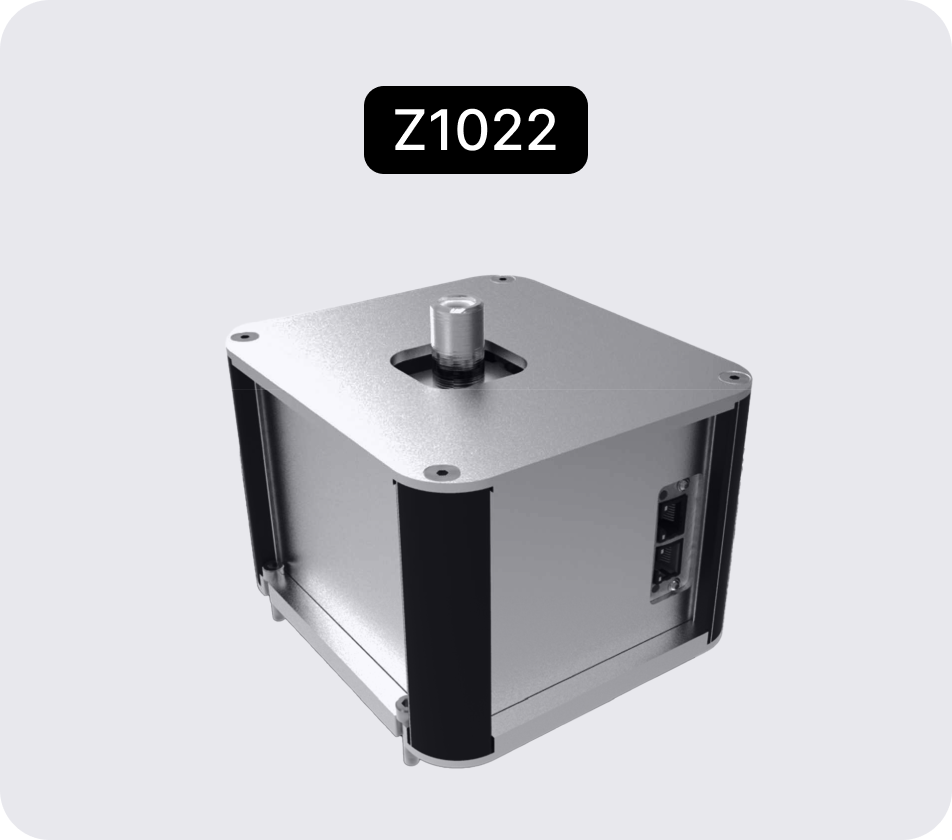
- Mobile measurement/determination of the robot TCP
- No integration with the robot controller required
- +/- 0,15mm
- Measuring ball in calotte
- WLAN
- RobCal-Software
- Industriebus (EtherCat, Ethernet/IP, ModBus, ProfiNet, …)
- Charger or 9V battery
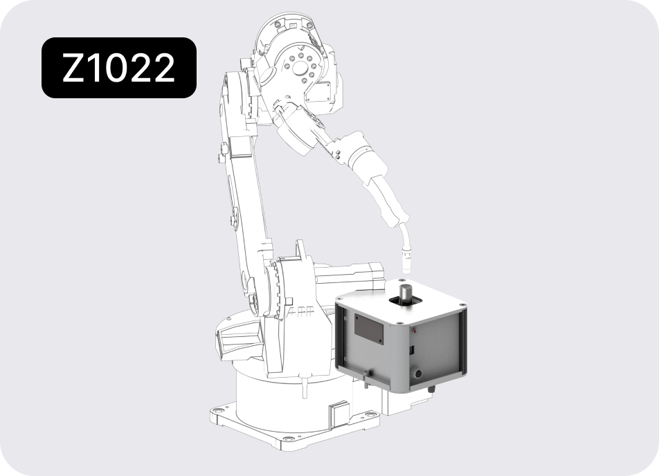
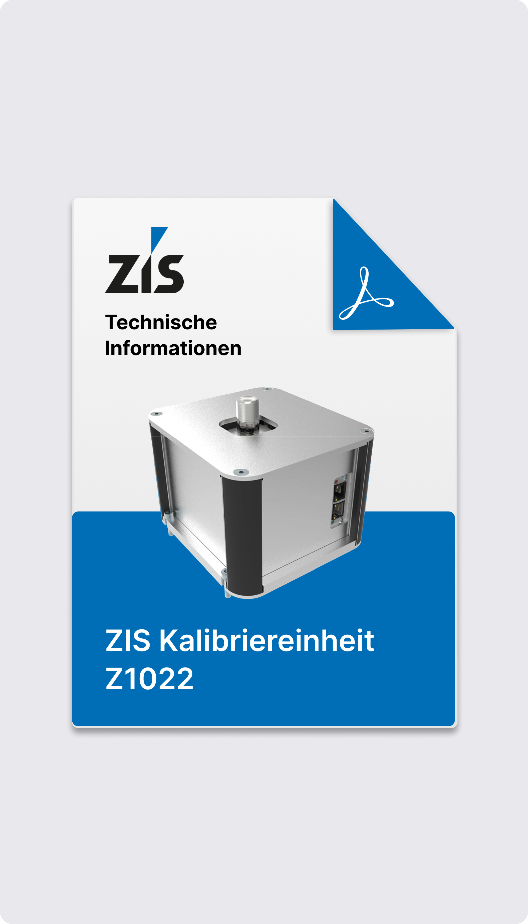
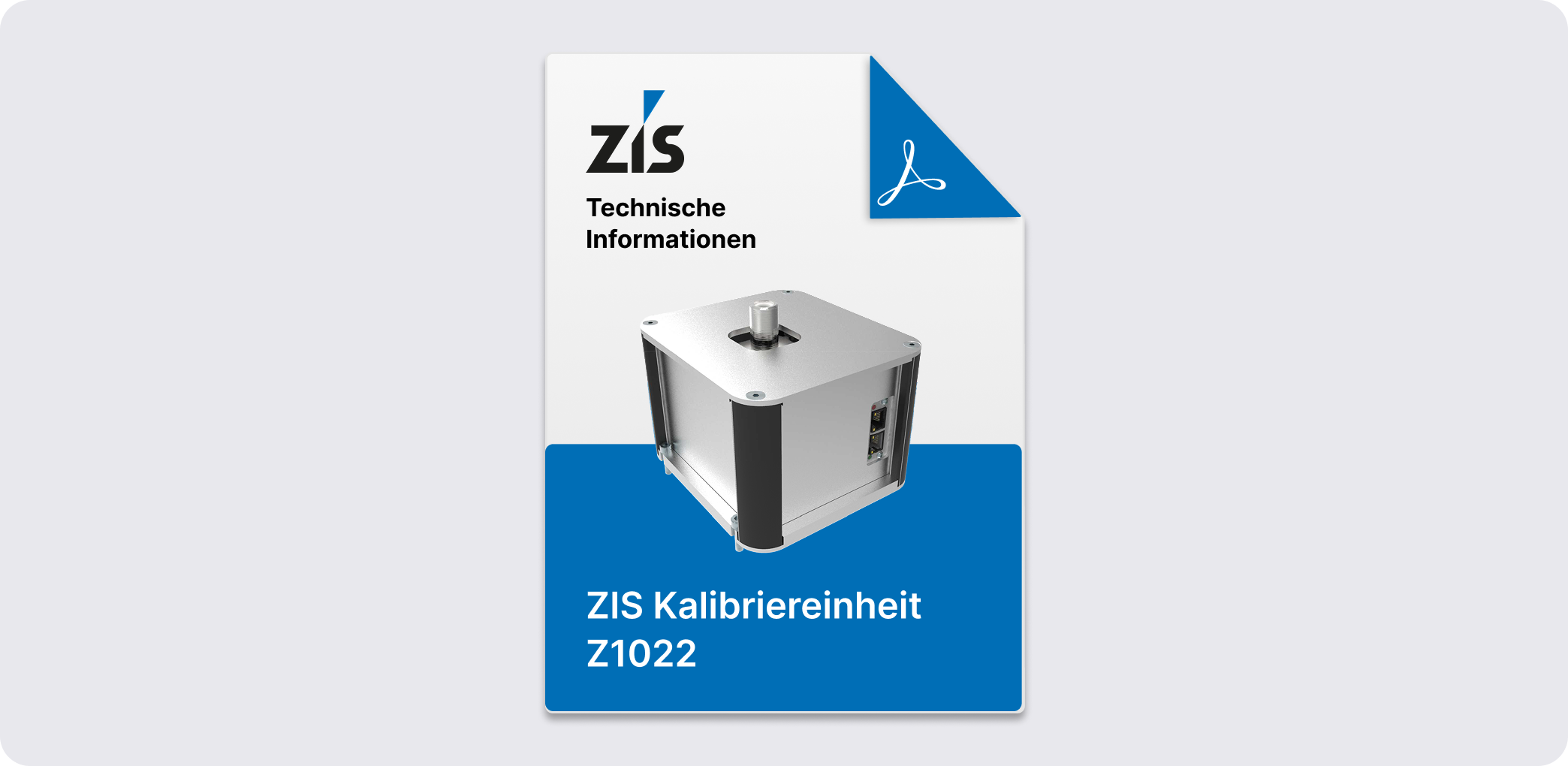
- Integration into the robot cell with a protocol for data exchange
- +/- 0,05mm
- Measuring ball in calotte
- Industrial bus (EtherCat, Ethernet/IP, ModBus, ProfiNet, …)
- USB
- RS232
- 24V connection with 8-pin connector
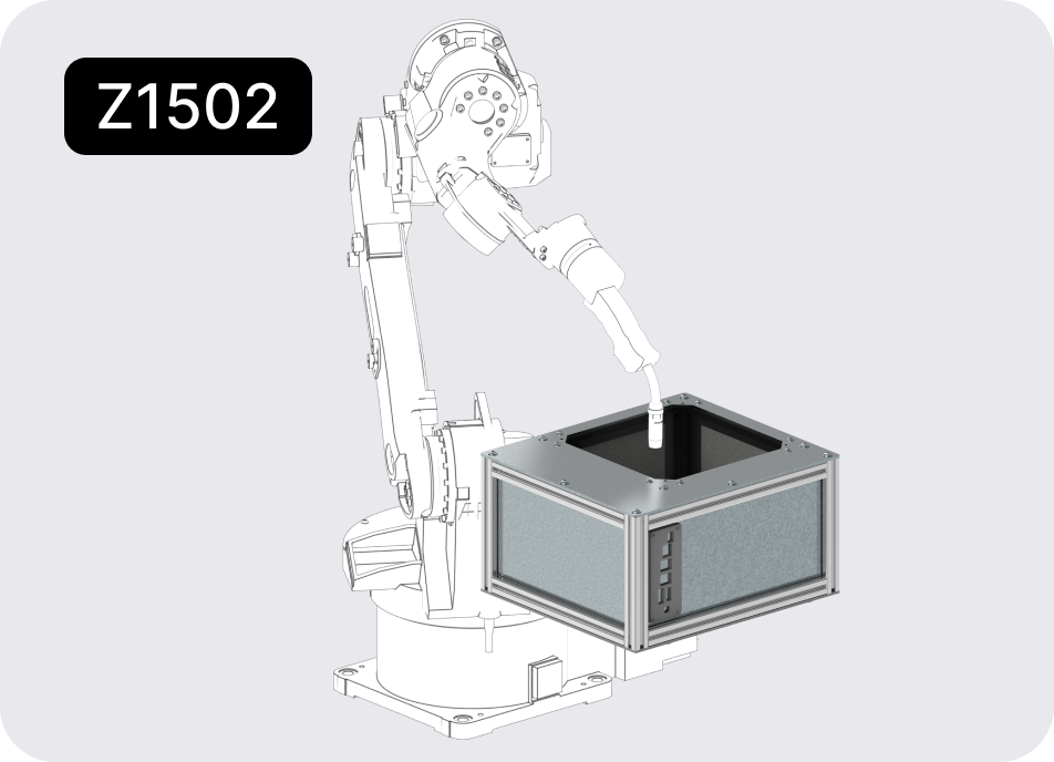
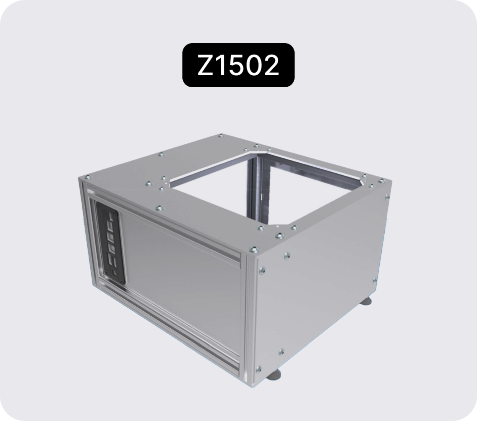
- Integration into the robot cell with regular fully automated measurement cycle
- Primarily intended for welding robots
- +/- 0,5mm
- Optical
- TCP/IP
- Industrial bus (EtherCat, Ethernet/IP, ModBus, ProfiNet, …)
- TCP/IP
- Evaluation is carried out internally and the results are transmitted to the controller.
Application area
- Mobile measurement/
determination of
the robot TCP - No integration with the robot controller required
- Integration into the robot cell with a protocol for data exchange
- Integration into the robot cell with regular fully automated measurement cycle
- Primarily intended for welding robots
Measurement accuracy
- +/- 0,15mm
- +/- 0,05mm
- +/- 0,5mm
Measuring principle
- Measuring ball in calotte
- Measuring ball in calotte
- Optical
Interfaces
- WLAN
- RobCal-Software
- Industrial bus (EtherCat, Ethernet/IP, ModBus, ProfiNet, …)
- USB
- RS232
- TCP/IP
- Industrial bus (EtherCat, Ethernet/IP, ModBus, ProfiNet, …)
Power
Source
- Charger or 9V battery
- Charger or 9V battery
- Charger or 9V battery
unabhängig
Selected answers
Robots are sequential kinematic structures with 6 drives arranged one behind the other. Because of this kinematic structure, a robot must move all 6 drives to achieve a simple linear movement.
Only the robot itself is delivered by the manufacturer; tools and clamps are then installed by system houses and users. In order for a robot to learn the necessary geometry of these tools, the TCP must be measured and the axes must be set to zero. This is called calibrating the robot.
TCP or Tool Center Point is the robot's tool or tool coordinate system. With a MAG torch, the tool center point is, for example, in the wire tip. Geometrically, the TCP or Tool Center Point represents the offset vector from the robot's flange coordinate system to the tool or tool coordinate system. In addition to axis calibration (setting the zero position of the robot's 6 drive axes), the measurement of the TCP is a prerequisite for exact robot calibration.
The TCP (Tool Center Point) can be measured using various variants:
- Multi-point calibration
With the TCP, the robot approaches the same point in space in various positions. The number of positions required depends on the type of robot used (KUKA 4 positions, FANUC — 3 or 6 positions). The robot automatically calculates the TCP based on these positions. - Measured tool
The tool is absolutely measured on an external device and the TCP values are manually transferred to the robot as coordinates.
In order to display various tools, the robot controllers allow various TCP values to be stored. When you select a tool, the associated TCP vector is also activated.
In practice, robotic measurement is associated with many difficulties for users. The ZIS robot calibration unit simplifies the measurement of the robot and allows user-independent repeatability. The following functions are supported for industrial robot calibration:
- For multi-point calibration, the calibration unit works like an electronic tip. The LED displays on the top show the user exactly how to move the robot to reach the starting position.
- With the help of the “RobCal” software, the device can be connected to a laptop via WiFi. By pivoting around the TCP, the accuracy of the calibration can be checked and recorded.
The data recorded by “RobCal” can be reused in the following form:
- Basis for calculating the robot's accuracy within the “RobCal” software by calculating the TCP deviation in the 3 main levels
- Saving as DXF format for further use/evaluation in a CAD system
- Printout of TCP accuracy in a PDF protocol for documentation to customers or for archiving.
Do you have any questions?
We will be happy to help you find the right solution.
