


Optical TCP Measurement - Z1502
Vorteile des Geräts auf einen Blick


- TCP/IP
- EtherCat, ModBus, ProfiNet, ...

So funktioniert unsere Kalibriereinheit
What our customers say

Pacific Research Laboratories, Inc.

Pacific Research Laboratories, Inc.
Pacific Research Laboratories, Inc.
Download the Z1502 data sheet now
Some answers
Robots are sequential kinematic structures consisting of 6 drives arranged in series. Due to this kinematic structure, a robot must move all 6 drives to execute a simple linear motion.
The manufacturer supplies only the robot itself; tools and grippers are subsequently attached by system integrators or end users. For a robot to recognize the necessary geometry of these tools, the TCP must be measured and the zero position of the axes must be set. This process is known as robot calibration.
The TCP, or Tool Center Point, refers to the robot's tool coordinate system. For a MAG welding torch, for example, the Tool Center Point is located at the tip of the wire. Geometrically, the TCP represents the offset vector from the robot's flange coordinate system to the tool coordinate system. In addition to axis calibration (setting the zero position of the robot's 6 drive axes), measuring the TCP is a prerequisite for precise robot calibration.
The TCP (Tool Center Point) can be calibrated using several different methods:
- Multi-point calibration
The robot approaches the same spatial point with the TCP in various orientations. The number of required orientations depends on the robot type used (KUKA – 4 orientations, FANUC – 3 or 6 orientations). Based on these orientations, the robot automatically calculates the TCP. - Calibrated tool
The tool is measured absolutely on an external device, and the TCP values are manually transferred to the robot as coordinates.
To accommodate different tools, robot controllers allow for the storage of various TCP values. Selecting a tool automatically activates its corresponding TCP vector.
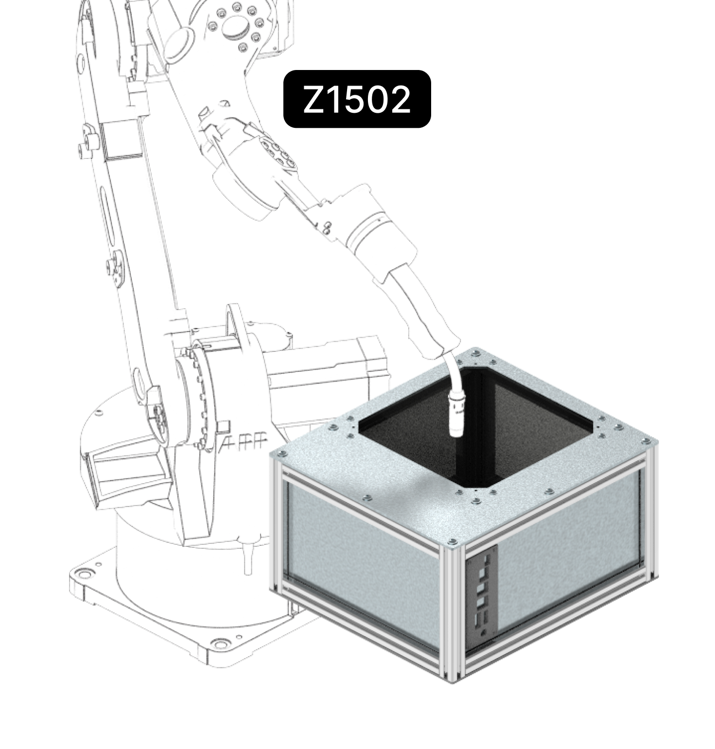
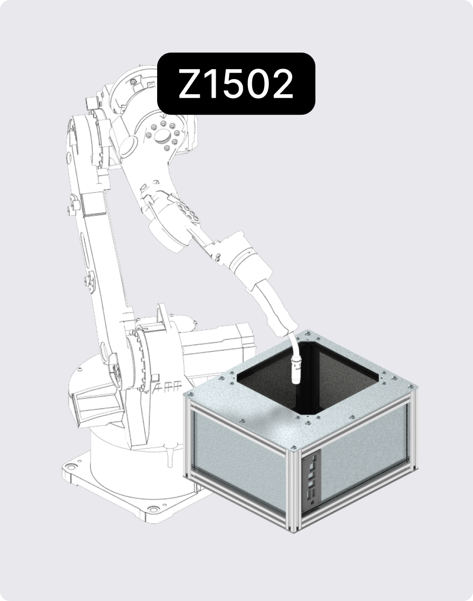
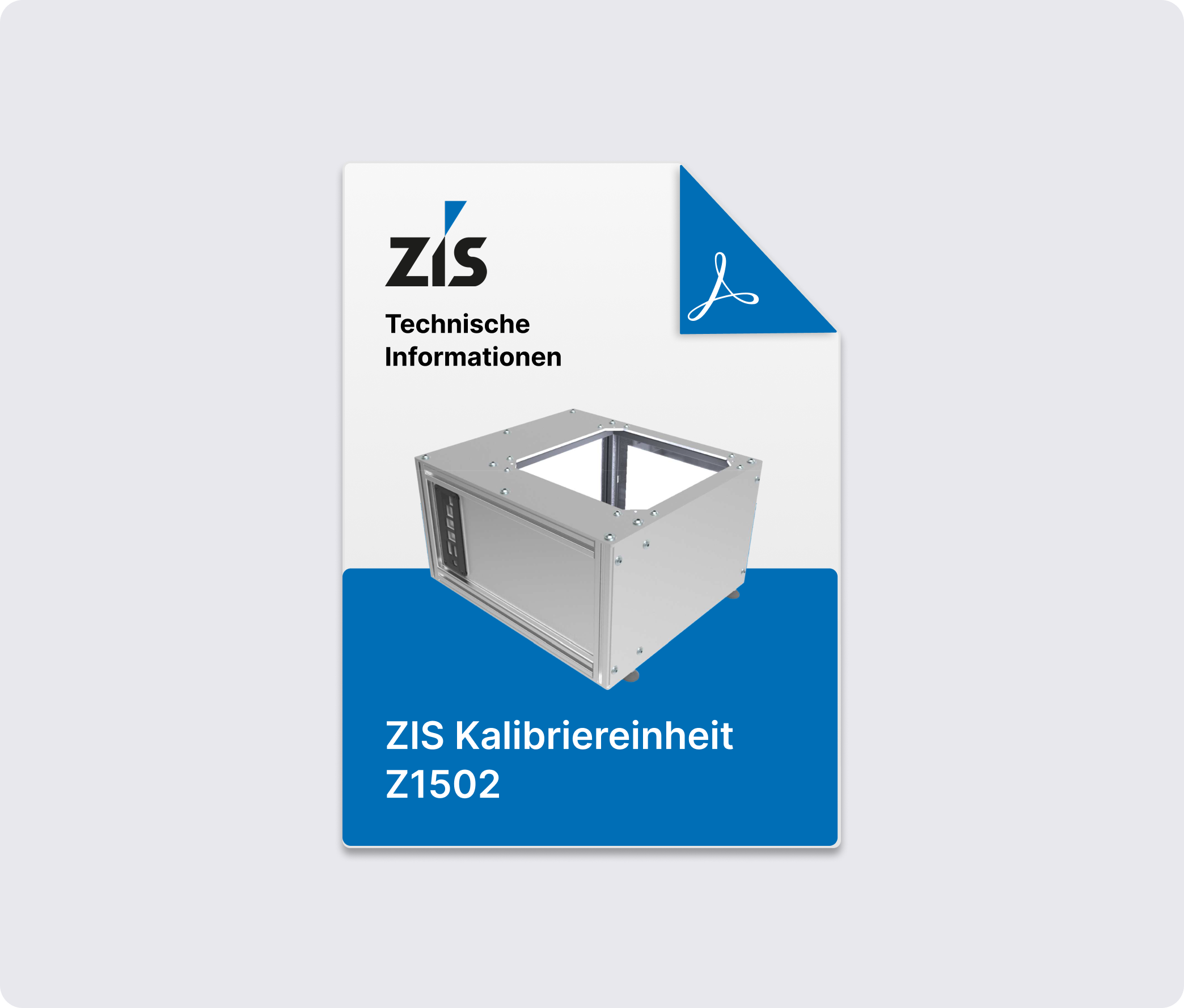
In practice, robot measurement often presents users with numerous challenges. The ZIS robot calibration unit simplifies the measurement process and ensures repeatable accuracy, regardless of the operator. The following functions are supported for industrial robot calibration:
- For multi-point calibration, the calibration unit functions as an electronic probe. The LED indicators on the top show the user exactly how to move the robot to reach the target position.
- The "RobCal" software allows the device to be connected to a laptop via WiFi. Calibration accuracy can be verified and recorded by performing a rotation around the TCP.
The data recorded by "RobCal" can be used in the following formats:
- Basis for calculating robot accuracy within the "RobCal" software by determining the TCP deviation across the 3 main planes
- Save as DXF format for further processing or analysis in a CAD system
- Displaying TCP accuracy in a PDF report for customer documentation or archiving purposes.
Do you have any questions?
We are happy to help you find the perfect fit.