


Robot calibration: why it is needed and which equipment you need
A robot is an open kinematic chain. Calibrating a robot means: setting the zero position of the 6 joints (axis calibration), defining the geometry of the tool used (TCP calibration), compensating possible tolerances of the robot (absolute calibration) and measuring the reference system for the robot program (workpiece calibration). The measurements build on each other and can therefore only be carried out one after the other.

- Robot calibration covers axis mastering, TCP measurement and, if needed, model-based calibration.
- The repeatability of a large industrial robot (ABB IRB 6700) is 0.04–0.06 mm; uncalibrated absolute accuracy is in the millimetre range.
- The measurements build on each other: first axis calibration, then TCP measurement, then absolute calibration if needed.
- A TCP measuring device measures and checks the tool; it does not support axis mastering or absolute accuracy.
What does robot calibration mean?
Robot calibration means determining the deviations between the controller's mathematical model and the real robot with its tool, and correcting them so that the robot hits programmed points and follows paths exactly. The closer the model matches reality, the more accurately the robot works.
The controller calculates every movement from joint angles, arm lengths and tool data. If one of these values is wrong, the TCP ends up next to the desired position. Bringing the model in line with reality is colloquially called “measuring the robot”.
Strictly speaking, calibration only determines the deviation, and adjustment then sets the system correctly (International Vocabulary of Metrology, VIM). In robotics, “calibration” means both. In practice, four levels are distinguished:
- Axis mastering: the zero position of each axis is stored in the controller. Without mastering, a robot moves to wrong points in space and cannot be jogged in Cartesian coordinates.
- Tool calibration (TCP): the tool center point is the origin of the tool coordinate system, e.g. the wire tip on a MAG torch. It is stored as an offset X, Y, Z and orientation A, B, C relative to the flange.
- Base and workpiece calibration: a coordinate system on the work surface, fixture or workpiece. At least 3 points (origin of the coordinate system and the direction of 2 axes) have to be defined. After moving a fixture or the workpiece, the points must be measured again, and the program can then continue to be used in the new reference system.
- Model-based calibration: an external measuring system, usually a laser tracker, records many positions; from them, the robot's deviations from its nominal dimensions are calculated. Fraunhofer IFAM uses more than 200 parameters for this, a study from ÉTS Montréal 34. Many manufacturers offer model-based calibration as an option. It increases the robot's accuracy, and the result is called an absolutely calibrated robot.
Axis mastering and TCP are mandatory for every industrial robot, because the manufacturer delivers it without a tool. How the TCP is determined is explained in the guide TCP calibration: methods and procedure.
Repeatability and absolute accuracy according to ISO 9283
Repeatability states how large the tolerance is when a robot approaches a position several times in succession; absolute accuracy states how close it gets to a specified target pose.
- Pose repeatability (RP): radius of a sphere around the center of the repeatedly reached positions. It is tested in the most used part of the workspace at five points, with at least 30 cycles from the same direction.
- Pose accuracy (AP): distance between target pose and the center of the reached poses, called “absolute accuracy” in practice.
Which parameter matters depends on the programming:
- Teach-in: the operator approaches every point on the real robot, the robot only repeats it. RP is decisive.
- Offline programming: the points come from CAD or simulation, and the robot has to hit a calculated pose. Absolute accuracy is decisive.
| Parameter | Value | Source |
|---|---|---|
| Repeatability FANUC LR Mate 200iC (small robot) | ±0.02 mm per manufacturer, measured ±0.009 to ±0.016 mm | University of Žilina |
| Repeatability ABB IRB 6700 (150–235 kg) | 0.04–0.06 mm | ABB data sheet |
| Position error, uncalibrated | up to several millimetres | Fraunhofer IFAM |
| ABB IRB 1600 before / after calibration (mean) | 0.979 mm / 0.329 mm | ÉTS Montréal |
| With ABB Absolute Accuracy option | approx. 0.5 mm in the entire workspace | ABB |
Repeatability is therefore one to two orders of magnitude better than a robot's absolute accuracy. Data sheet values only apply under test conditions: in Žilina, repeatability got worse as the arm reach increased.
Important: A small mastering error acts via the lever arm. A zero-point error of 0.01° shifts a TCP at 2,000 mm distance by 2,000 mm × 0.01° × π/180 ≈ 0.35 mm, six to nine times the repeatability of an ABB IRB 6700.
When does a robot need to be calibrated?
A robot needs to be mastered or measured again as soon as the position of an axis, the tool or the position of robot and workpiece relative to each other has changed.
The mastering column follows the KUKA documentation for System Software 8.3; RDC is the encoder electronics.
| Occasion | Axis mastering | TCP | Base | Kinematic model |
|---|---|---|---|---|
| Commissioning | yes | yes, per tool | yes | for offline programming |
| Motor or RDC replacement | yes | check | – | as specified by the manufacturer |
| Gearbox replacement | yes, delete old data first | check | – | as specified by the manufacturer |
| Collision, impact on end stop above 250 mm/s | yes | yes | check | check |
| Axes moved without controller | yes | – | – | – |
| New tool | offset for new load | yes | – | – |
| Wear part replaced, e.g. nozzle | – | check | – | – |
| Robot or fixture moved | – | – | yes | redetermine position in the cell |
| Switch to offline programming | check | yes | yes | yes |
Important: First the axes are mastered, then the TCP is measured, then the base is calibrated. Because the controller uses the axis data to calculate the TCP, faulty mastering also produces faulty TCP values. The mastering error is reflected in the TCP error.
The load also affects mastering, because the tool deforms the robot structure. KUKA therefore works in three stages:
- First mastering: without tool, workpiece and supplementary load.
- Teach offset: stored for each load; a gripper for heavy parts needs it with and without workpiece.
- Load mastering with offset: restores the first mastering after a motor replacement or collision without removing the tool.
Measuring equipment for calibration and mastering
Each calibration level has its own measuring equipment; no single device covers all four.
- Axis mastering: mastering aid from the robot manufacturer, at KUKA an electronic probe (SEMD, MEMD) in the gauge cartridge of each axis or a dial gauge, at ABB e.g. the calibration pendulum.
- TCP with on-board means: fixed reference tip and the controller's multi-point method, such as KUKA XYZ 4-Point or the FANUC 3-point or 6-point method. The result depends on how precisely the operator hits the tip.
- TCP with a measuring device: tactile with a ball in a calotte, mobile or permanently installed, or optically with a camera in the cell.
- Base: measured tool and 3-point method; accuracy depends on mastering and TCP.
- Kinematic model: laser tracker or optical measuring system with evaluation software. Mean residual error afterwards approx. 0.3–0.5 mm (ABB, ÉTS); ÉTS validated with around 1,000 measurements.
Tip: The measuring equipment must be at least one order of magnitude more accurate than the quantity being checked. To measure a repeatability of ±0.02 mm, the University of Žilina therefore chose equipment that measures at least ten times more accurately.
Procedure: robot calibration in five steps
Robot calibration follows a fixed order, because each level builds on the previous one.
- Define the goal: teach-in needs repeatability, offline programming needs absolute accuracy. This determines whether the kinematic model has to be calibrated.
- Check or reset axis mastering: first mastering without load, then an offset for each load under the same ambient conditions, such as the same temperature. After a gearbox replacement, delete the old mastering data first.
- Measure the TCP for each tool and check it by rotating: if the tip stays on one point when reoriented, the TCP is correct.
- Calibrate the base: only with an already measured tool.
- Document: back up mastering, tool and base data, file the report, set the TCP inspection interval for each process.
Steps 2 to 4 can be done with the robot manufacturer's accessories and a TCP measuring device.
What a TCP measuring device can and cannot do
A TCP measuring device determines and checks the position of the tool tip relative to the flange; it does not correct axis mastering or absolute accuracy in the workspace.
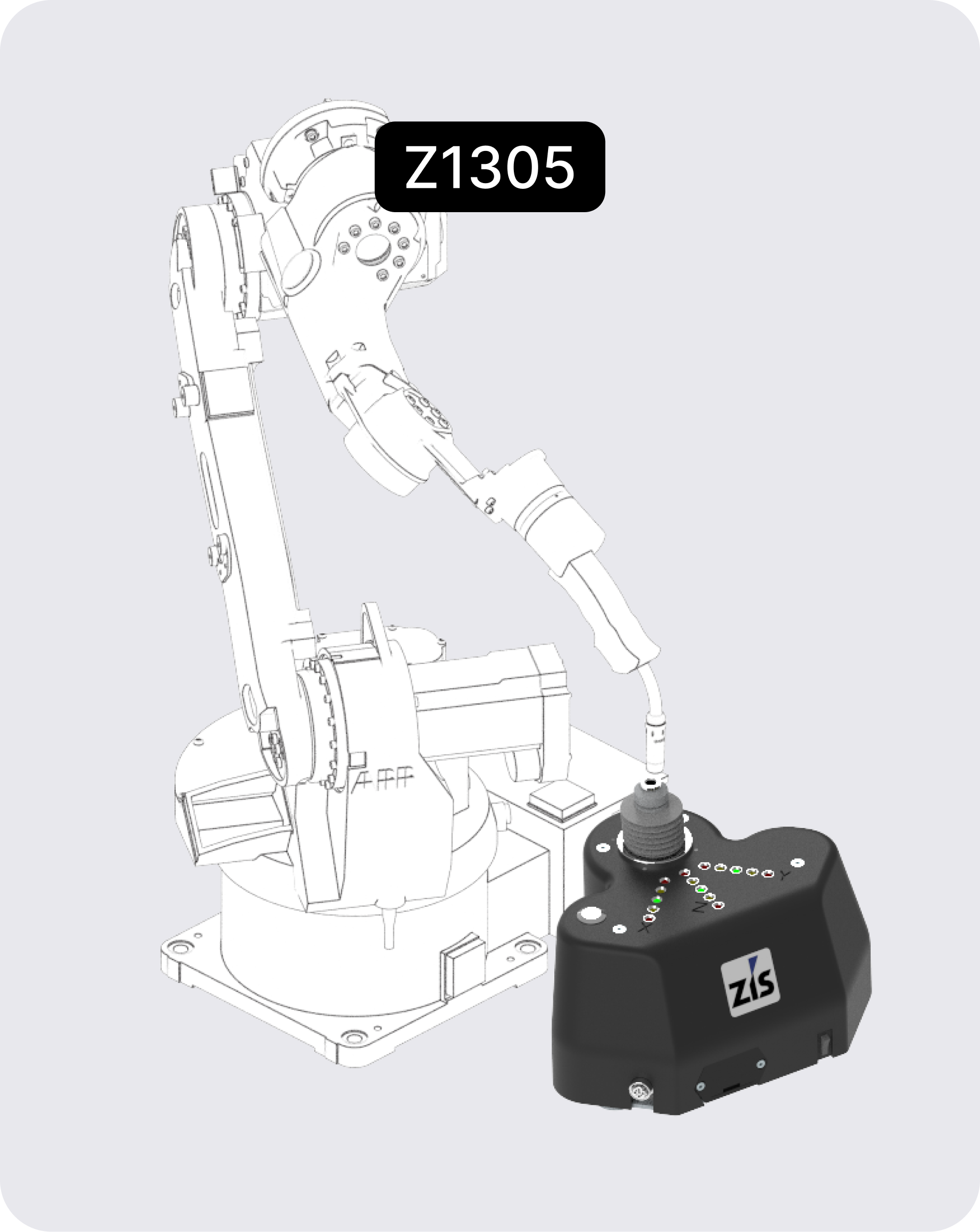
ZIS Industrietechnik GmbH builds three types:
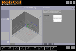
- Z1305, mobile TCP measuring device: ball in calotte, < 0.15 mm. LEDs show how the robot has to move; in the multi-point method it serves as an electronic tip without integration into the controller. In addition, the device can be connected to a laptop via Wi-Fi. The supplied RobCal software then checks the accuracy of the calibration. For this, the path of the TCP is recorded while rotating about it. If the path describes a circle, the TCP is off by the radius of the circle. The software helps evaluate the TCP error.
- Z1022, fixed installation: ball in calotte, < 0.05 mm, data exchange with the PLC via a fieldbus selected by the customer; ZIS provides the protocol for the data exchange.
- Z1502, optical: < 0.5 mm, measures within the cycle and sends the new TCP value directly to the robot, mainly for welding robots.
Not covered:
- Axis mastering: the zero position is set with the robot manufacturer's mastering aid.
- Kinematic model: arm length and angle errors remain; this needs a measuring system that records many positions.
- Entire workspace: the rotation check shows the stability of the TCP at one location.
Which type suits which application is shown in the overview of ZIS TCP measuring devices.
Conclusion
Both teach-in applications and offline-programmed applications require exact axis and TCP calibration. Model-based calibration with a laser tracker or optical measuring system (absolute calibration) can increase the robot's accuracy. After a motor or gearbox replacement and after a collision, axis mastering comes first, followed by a TCP check. Keeping to the order mastering, TCP, base and documenting each level makes later deviations easier to find.
Frequently asked questions
How often does a robot need to be calibrated?
For axis mastering, the manufacturer documents reviewed give no fixed interval but occasions such as motor replacement or collision. Users also check the TCP regularly, because the tool can change during operation. Another factor is how severe the consequential damage of a wrongly calibrated robot would be. In principle, both the required calibration accuracy and the frequency depend on the application.
Does the TCP have to be measured again after a motor replacement?
First the affected axis must be mastered; the TCP data describe the tool relative to the flange and remain valid as long as the tool is unchanged. Rotating about the TCP then shows whether the tip stays on the point when reoriented.
What does “KUKA calibration” mean?
Usually mastering is meant: an electronic probe (SEMD or MEMD) on the gauge cartridge records the zero position when passing the reference notch, alternatively a dial gauge. How the tool is taught on KUKA, FANUC and ABB controllers is shown in the guide TCP teach-in on KUKA, FANUC and ABB.
Does a robot need to be recalibrated after relocation?
Base and workpiece coordinate systems must be measured again; axis mastering only if an occasion such as moving axes without the controller occurs. With offline programming, the position of the robot in the cell must also be redetermined, called “Cell Alignment” at ABB.
Why does an offline-programmed robot miss the points?
The simulation calculates with nominal dimensions, while the real robot deviates due to manufacturing tolerances and deflection, typically by 8–15 mm according to ABB. Remedies are a base measured on the workpiece and model-based calibration or the manufacturer's absolute accuracy option.
Can a robot be calibrated without a measuring device?
Mastering and TCP can be done with the manufacturer's accessories and the multi-point method, although the result depends on how precisely the operator hits the tip. Absolute accuracy in the workspace requires an external measuring system.
Sources
- DIN EN ISO 9283:1999-05 Manipulating industrial robots – Performance criteria and related test methods (ISO 9283:1998), table of contents, DIN e. V., Mechanical Engineering Standards Committee, accessed 27 Oct 2026
- Kuric, I. et al.: Measurement of industrial robot pose repeatability, MATEC Web of Conferences 244, 01015 (2018), University of Žilina, Faculty of Mechanical Engineering, accessed 27 Oct 2026
- KUKA System Software 8.3 – Operating and Programming Instructions for System Integrators (as of 14 Jan 2015), chapters 5.8 Mastering and 5.10 Calibration (available to customers via KUKA Xpert), KUKA Roboter GmbH, accessed 27 Oct 2026
- Absolute Accuracy – Industrial Robot Option (PR10072EN_R4, 2005), ABB Inc., accessed 27 Oct 2026
- IRB 6700 – data sheet (ROB0252EN_A, 2013), ABB Robotics, accessed 27 Oct 2026
- Model-based calibration of industrial robots, Fraunhofer Institute for Manufacturing Technology and Advanced Materials IFAM, accessed 27 Oct 2026
- Nubiola, A.: Étalonnage d’un robot sériel avec un système de laser de poursuite (master's thesis, 2011), École de technologie supérieure, Montréal, accessed 27 Oct 2026
- International Vocabulary of Metrology (VIM 3), term 2.39 “calibration” and its distinction from 3.11 “adjustment”, Joint Committee for Guides in Metrology (JCGM) / BIPM, accessed 27 Oct 2026