


TCP calibration: measuring the tool center point, methods and procedure
Calibrating the TCP means giving the robot controller the exact position of the tool center point relative to the robot flange. The tool tip approaches a fixed point from several directions, externally measured values are entered, or a measuring device determines the TCP by touch or optically. Rotating about the TCP then checks the result.

- The TCP is the origin of the tool coordinate system; on a MAG welding torch it is the wire tip.
- The multi-point method needs 3 to 6 positions: KUKA 4, FANUC 3 or 6, Universal Robots at least 3. As a rule, the more points, the more accurate the TCP measurement.
- A measuring device such as the ZIS Z1305 replaces the operator's eye: LEDs show the direction in X, Y and Z. In addition, TCP accuracy can be checked efficiently.
- Measure again after a collision, tool change, maintenance or quality deviation, and always rotate about the TCP afterwards.
What is the TCP of a robot?
The TCP (tool center point) is the working point of the tool to which the robot controller refers all movements.
The TCP is the origin of the tool coordinate system. Geometrically, it describes the offset from the flange, the tool mount on the last axis, to the tool: three values for the position (X, Y, Z) and three for the orientation [1]. On a MAG welding torch, the TCP is at the wire tip; on plasma and oxyfuel torches, it lies on the extension of the torch's center axis. This extension defines the distance to the workpiece in the working position.
TCP calibration, TCP measurement and TCP determination all mean the same process: the real position of the point is determined and stored as tool data. Controllers manage several TCPs; selecting a tool activates the matching one [1]. The coordinate systems of industrial robots are defined in ISO 9787 [2].
Why an inaccurate TCP degrades path and process
An inaccurate TCP shifts the tool tip away from the programmed path, most of all when the tool is reoriented.
When rotating, the controller uses the stored TCP as the pivot [1]. If the real tip is off by the error e, it moves on a circle; after a rotation by the angle θ the offset is s = 2 · e · sin(θ/2). Only the part of the error perpendicular to the rotation axis counts.
Example for a TCP error of 1 mm:
- 30° rotation: 0.52 mm offset
- 90° rotation: 1.41 mm offset
- 180° rotation: 2.00 mm offset
Consequences in welding and flame cutting
- Wobbling torch: especially at corners such as a profile bent by 90°; the distance between contact tip and workpiece varies uncontrollably [3].
- Bent wire: the arc may not ignite or the weld is offset; an interruption on the path can make the part unusable [3].
- Flame cutting: a position error shifts the cut edge, an orientation error changes the bevel angle.
Which deviation is tolerable depends on the process. In both cutting and welding, an offset of less than 1 mm can already be unacceptable.
Important: Teach-in programs, i.e. points approached and stored on the real workpiece, hide a TCP error as long as the orientation stays the same. Paths from CAD/CAM data, for example for 3D flame cutting, always need a measured TCP.
Overview of TCP calibration methods
Five methods are common: the controller's multi-point method, externally measured values, a tactile measuring device, the light barrier and the camera.
Multi-point method of the controller
The operator moves the tool tip to a fixed reference tip from several orientations; the controller calculates the TCP from them. Most industrial robots have this method built in [3]. Required positions:
- KUKA: 4 positions
- FANUC: 3 or 6 positions
- Universal Robots: at least 3 positions, a fourth for checking [1]
Accuracy depends on the operator's eye: positioning tips manually is common, higher accuracy requires sensors [4]. Jogging with the teach pendant also takes time [5]. Procedures per controller: TCP teach-in on KUKA, FANUC and ABB.
Tip: Choose positions with the largest possible differences in orientation. If they are too similar, the calculation fails [1]; reference tip and tool must be firmly fixed.
Externally measured tool
The tool is measured absolutely on a fixture outside the robot, or the values come from the design (CAD); the operator enters them manually. Tolerances that only arise when mounting on the flange are not captured this way.
Tactile measuring device: measuring ball in a calotte
The robot guides a measuring ball into a spherical counter surface of the device, the calotte. The ball sits on an adapter that exists for every tool; on cutting and welding torches it replaces the nozzle. The device records the position of the ball in X, Y and Z and thus replaces the operator's eye. The mobile ZIS Z1305 and the fixed Z1022 work on this principle.
Non-contact: light barrier and laser
The tool tip passes through one or two crossed light beams from several directions; from the interruption points the system calculates the TCP, but needs several search runs [5]. A prototype from Kielce University of Technology with two laser beams (at most 1 mm in diameter) detected the welding wire with deviations in the range of tenths of a millimetre [3].
Camera and optical methods
Cameras capture the tool, and image processing detects contour, position and orientation. A system from the University of Belgrade with two cameras also detected deformed tools and measures most accurately in the center of the image; sources of error are lighting, dust and rotationally symmetric tools [5]. The ZIS Z1502 measures on this principle in an automatic cycle.
Comparison of methods
| Method | Who finds the point | Automatic in the cycle | Accuracy depends on |
|---|---|---|---|
| Multi-point method | Operator by eye | no | Eye, number and spread of positions |
| Externally measured | Fixture or CAD data | no | Fixture, mounting tolerances at the flange |
| Tactile: ball in calotte | Measuring device | with a fixed device | Measuring device (values see device overview) |
| Light barrier, laser | Sensor | yes | Beam diameter, search runs |
| Camera, optical | Image processing | yes | Optics, lighting, contamination |
Calibrating the TCP with a measuring device: 8 steps
With a measuring device such as the ZIS Z1305, an electronic tip replaces the operator's eye in the multi-point method; rotating about the TCP then checks the result.
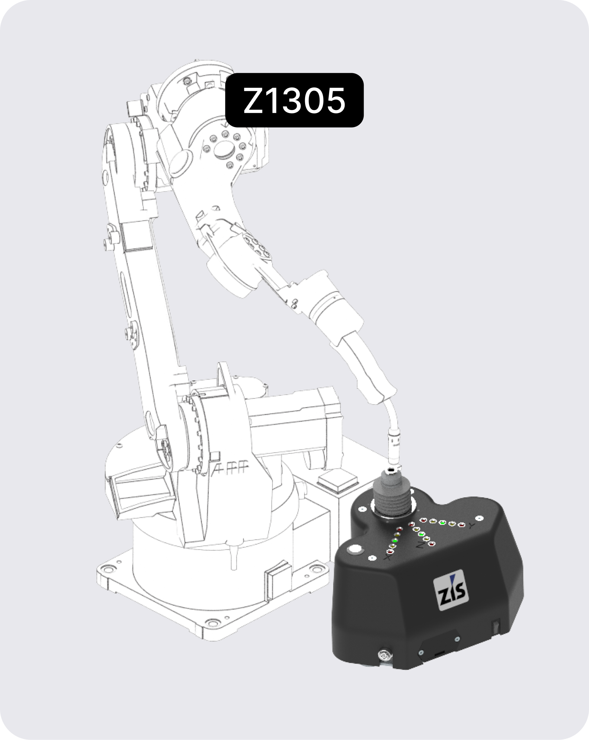
- Prepare the tool: bring it into working condition, mount the adapter with the measuring ball (on cutting and welding torches in place of the nozzle), select the tool number.
- Set up the device: ensure it can be reached from clearly different orientations; magnetic feet secure the Z1305 calibration unit against shifting.
- Select manual mode: at reduced speed, as people may be within reach [1].
- Approach the first position: guide the ball into the calotte; the LEDs for X, Y and Z show the direction to move; bring all LED displays to “green”; save the position in the controller.
- Further positions: change the orientation clearly and approach the same measuring position until the controller has enough positions.
- Calculate the TCP: save the value under the tool number. A small residual error only shows that the positions fit together; Universal Robots rates each position green, yellow or red [1].
- Check by rotating: connect RobCal via Wi-Fi and rotate about the new TCP, ideally about all three axes. RobCal records the path and calculates the deviation in the 3 main planes; if it exceeds the tolerance, repeat steps 4 to 6.
- Document: save the measurement report as PDF, export measurement data as DXF if needed.
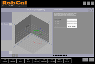
Important: Rotate about the new TCP after every measurement. If the tip stays in place, the TCP is correct; a small residual error in the controller alone does not prove it.
A measurement with the Z1305 takes about 5 minutes. Data sheet: Z1305 mobile TCP measuring device.
When to measure the TCP again
Measure again whenever the geometry between flange and tool tip may have changed.
- Collision: an impact can bend the tool, torch neck or wire [3].
- Tool, torch or nozzle change: every spare part has its own tolerances; the stored TCP only applies to the measured unit.
- Maintenance: after work on the tool, tool mount or robot wrist and after axis mastering.
- Quality deviation: weld or cut is offset, the distance between contact tip and workpiece varies at corners [3], or the bevel angle is wrong.
- New offline programs: before the first run of paths from CAD/CAM data.
Robots under continuous load have to be calibrated repeatedly [4]. A fixed inspection interval can hardly be given, because a wrong TCP usually leads to process errors immediately. As a rule: recalibrate the TCP after every intervention or fault in the system, such as a tool change or collision.
TCP calibration and robot calibration: the difference
TCP calibration measures only the tool; robot calibration also covers the axes.
This includes the zero position of the axes (mastering) and, depending on requirements, absolute accuracy: how precisely the robot reaches a specified position in space. Robots repeat positions very precisely but position less accurately in absolute terms [4]. A TCP measuring device only corrects the tool data; more in the guide Robot calibration.
Which ZIS device for which task?
The Z1305 measures robots of all brands as a mobile device, the Z1022 is permanently installed with PLC connection, the Z1502 checks optically within the cycle.
| Device | Design and measuring principle | Accuracy | Connection | Typical task |
|---|---|---|---|---|
| Z1305 | mobile, ball in calotte, LED display X, Y, Z | < 0.15 mm | Wi-Fi to the RobCal software, no software on the robot | Commissioning, service, check after collision; PDF report |
| Z1022 | fixed installation, rugged housing, ball in calotte | < 0.05 mm | PLC or machine control via fieldbus (EtherCAT, EtherNet/IP, Modbus, PROFINET and others), USB, RS232 | automatic TCP measurement in systems |
| Z1502 | optical, in the robot cell | < 0.5 mm | TCP/IP, EtherCAT, Modbus, PROFINET and others; evaluation in the device | fully automatic cycle without tool change, mainly welding robots; one image in under 5 s |
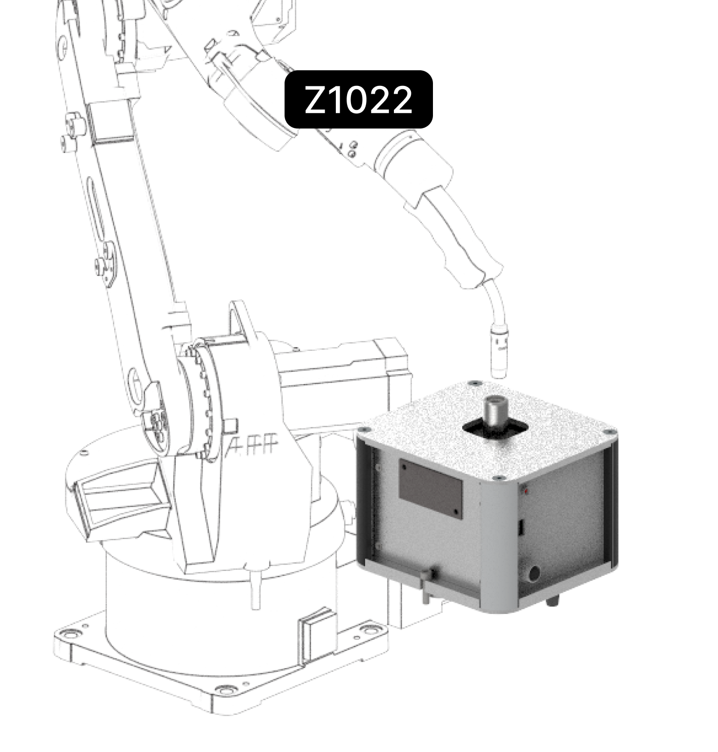
All devices with data sheets: overview of TCP measuring devices for robots. To find out which device suits your process, contact ZIS Industrietechnik.
Conclusion
For single robots with rare tool changes, the controller's multi-point method is sufficient if you check the result by rotating. If you look after several robots or need operator-independent results or reports for customers, use a mobile measuring device such as the Z1305. For regular checks without an operator, the permanently installed Z1022 or the optical Z1502 are suitable. Measure again after every collision, every tool change and whenever quality deviates.
Frequently asked questions
What is the difference between the TCP and the base coordinate system?
The TCP describes the tool relative to the flange, the base or user coordinate system the position of workpiece or fixture in space. A wrong base shifts the whole path, a wrong TCP shows mainly when reorienting.
Does the tool orientation have to be measured as well?
Often the operator only defines the position, and the orientation then matches that of the flange [3]. If the tool points at an angle to the flange axis, for example with an angled torch neck, the orientation must be determined with additional positions.
How accurate does the TCP have to be for welding or flame cutting?
That depends on process, weld type and part. Often an error of less than 1 mm is already a problem. The actual deviation is shown by the rotation test; RobCal reports it for the Z1305 in the 3 main planes.
How long does a TCP calibration take?
Manually, the time depends on the operator and the number of positions; with the Z1305 a measurement takes about 5 minutes. The optical Z1502 calibration unit analyses the tool position in less than 5 seconds.
Do I need software on the robot for a TCP measuring device?
Not for the Z1305: the LEDs show the direction, and the evaluation runs in RobCal on the laptop. The Z1022 and Z1502 are integrated into the system control via fieldbus or interface.
Sources
- e-Series Software Handbook, PolyScope 5.24 (ch. 1.10 Modes, 5.1 TCP Configuration, 6 Move Tab), Universal Robots A/S, accessed 27 Oct 2026
- ISO 9787:2013 Robots and robotic devices – Coordinate systems and motion nomenclatures, International Organization for Standardization (ISO), accessed 27 Oct 2026
- J. Zwierzchowski: A Device for Automatic Robot Tool Center Point (TCP) Calibration Adjustment for the ABB Industrial Robots, Engineering Mechanics 2017, pp. 1138–1141, Kielce University of Technology / Institute of Thermomechanics, Czech Academy of Sciences, accessed 27 Oct 2026
- J. Konecny et al.: Industrial camera model positioned on an effector for automated tool center point calibration, Scientific Reports 14, 323 (2024), Springer Nature, accessed 27 Oct 2026
- Z. Gordić, C. Ongaro: Calibration of Robot Tool Centre Point using Camera-based System, Serbian Journal of Electrical Engineering 13 (1), 2016, pp. 9–20, Faculty of Technical Sciences Čačak, University of Kragujevac, accessed 27 Oct 2026