


TCP teach-in on KUKA, FANUC and ABB: methods and procedure
On KUKA, the TCP is taught via Start-up > Calibrate > Tool > XYZ 4-Point: the tool tip approaches a fixed reference point from four clearly different directions, and the controller calculates the TCP from them. FANUC uses Three Point (3 points) or Six Point (6 points), ABB the Define function with usually 4 approach points.

- KUKA: XYZ 4-Point determines the TCP position from 4 positions; ABC World or ABC 2-Point defines the orientation.
- FANUC: Three Point determines only the position with 3 points, Six Point also the orientation with 6 points.
- ABB: Define with TCP, TCP&Z or TCP&Z,X; 4 approach points are usually enough, and Mean Error and Max Error are displayed.
- Clearly different orientations and an exactly hit point in space are decisive.
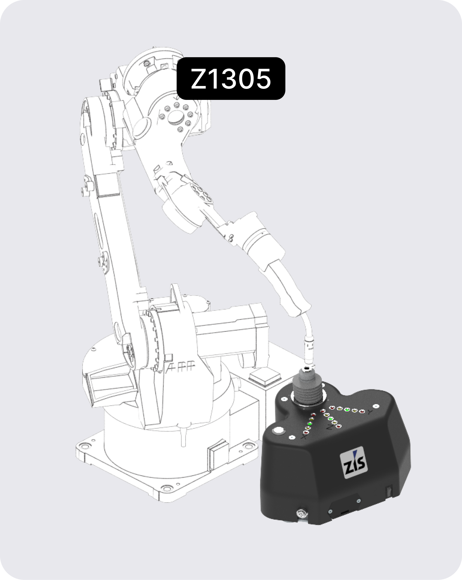
- The ZIS Z1305 shows by LED when the measuring position is reached; reorienting about the TCP checks the result with the RobCal software.
TCP teach-in: principle and basic rules for all controllers
Teaching the TCP on KUKA, FANUC and ABB means: the tool tip approaches a fixed point in space in several positions, and the controller calculates the position of the TCP from the flange positions [1].
The TCP (tool center point) is the origin of the tool coordinate system. What it means and which other measuring methods exist is explained in the guide TCP calibration: methods and procedure.
- Position (X, Y, Z): several positions with different orientations on the same point in space.
- Orientation: additional points or alignment with the world axes. Needed if the tool does not work in the direction of the flange axis, for example with an angled torch [4].
The same basic rules apply to all three manufacturers:
- Exactly the same point in space: every deviation enters the calculation. Move the last millimetres in small steps [5].
- Fixed reference tip: the tip stands firmly on a stable base and stays in the same place for all positions [2].
- Tool in working condition: the TCP is the point at which the tool performs the process. On a welding torch, for example, the stick-out length must be taken into account correctly.
- Measuring location in the workspace: the robot measures with its own kinematics; the result fits the area in which you measure [5]. If the error values stay high despite careful approach, axis mastering may be the cause, see the guide Robot calibration.
- The eye as a limit: without aids, the result depends on the operator's eye.
Important: Change the orientation clearly between positions and move away from the reference point in between. KUKA requires flange positions that are far enough apart [1], ABB rates pure reorientation as worse [5]. For the most accurate measurement, avoid positions close to singularity and in different quadrants.
TCP teach-in on KUKA: XYZ 4-Point and other methods
On KUKA (KUKA System Software 8), you teach the TCP under Start-up > Calibrate > Tool, for the position with XYZ 4-Point or XYZ Reference [1].
Prerequisite: the tool is mounted on the flange and operating mode T1 is selected [1].
XYZ 4-Point step by step
- Select Start-up > Calibrate > Tool > XYZ 4-Point, assign number and name, confirm with Next [1].
- Move the TCP to the reference point, press Calibrate, answer the safety prompt with Yes [1].
- Move away, change the orientation clearly, approach the same point from another direction and calibrate. Repeat until four positions are saved [1].
- Enter load data or skip if they are entered separately [1].
- Read the result: X, Y, Z and an error value in mm [2]. The Measuring points button shows the four flange positions [1].
- Save, or define the orientation directly with ABC World or ABC 2-Point [1].
Important: A new calibration overwrites the data under the selected tool number. Check beforehand which numbers are in use [2].
Other methods on KUKA
- XYZ Reference (2 measurements): TCP of a new tool by comparison with an already measured one [1]. Both tools approach the same reference point one after the other, which must not move in between.
- ABC World (1 measurement): align the tool axes with the world axes. 5D defines the working direction (+X tool parallel to −Z world), 6D additionally +Y parallel to +Y and +Z parallel to +X of the world [1].
- ABC 2-Point (3 measurements): TCP on the reference point, then bring the reference point onto the X axis at a negative X value, then into the XY plane at a positive Y value. Intended for the most accurate axis directions [1].
- Numeric input: enter X, Y, Z and A, B, C relative to the flange, e.g. from CAD or an external measurement [1].
- Typical errors: positions too similar, wrong tool number, ABC 2-Point with a working direction other than the standard X [1] [2].
FANUC: TCP teach-in with Three Point, Six Point or Direct Entry
On FANUC, you set up the TCP as a Tool Frame: MENU > SETUP > F1 [TYPE] > Frames > F3 [OTHER] > Tool Frame, then F2 DETAIL and F2 [METHOD] [4].
Three Point, Six Point (XY or XZ) and Direct Entry are available; further methods depend on the software version [4].
Three Point: position only
- Move the tool tip precisely and centrally to the reference tip [4].
- Record Approach Point 1 with SHIFT + RECORD; the status changes from UNINIT to RECORDED [4].
- Change the orientation and record Approach Points 2 and 3. FANUC America recommends rotations of about 0°, 180° and 90° [3].
- When USED is shown, the Tool Frame is calculated [4].
The orientation remains that of the flange. If the tool works at an angle to the Z axis of the flange, the textbook recommends Six Point [4].
Six Point: position and orientation
- Record Approach Points 1 to 3 as for Three Point [4].
- Orient Origin Point: record the tool in the desired orientation of the new coordinate system.
- X Direction Point: move in the +X direction of the tool and record.
- Return to the Orient Origin Point with SHIFT + MOVE_TO, then move in +Z (XZ) or +Y (XY) and record.
- Direct Entry: enter known values without moving the robot [4].
- Typical errors: points still at UNINIT or RECORDED instead of USED; robot moved by mistake, then return to the recorded point with SHIFT + MOVE_TO [4].
ABB: defining the TCP with TCP, TCP&Z and TCP&Z,X
On ABB (IRC5 with FlexPendant), you define the TCP in the tool data via Jogging > Tool > Edit > Define [5].
- TCP (default orient.): position only; orientation as the robot's mounting plate.
- TCP&Z: additionally the direction of the Z axis.
- TCP&Z,X: additionally the directions of the Z and X axes [5].
Procedure on the FlexPendant
- Select the tool, Edit > Define, choose method and number of approach points; 4 are usually enough [5].
- Move point A in small steps as close as possible to the reference point and accept with Modify Position [5].
- For B, C and D, move away each time and return in a new orientation [5].
- For TCP&Z and TCP&Z,X, record the elongator points: without changing the orientation, bring the reference point onto the desired positive tool axis [5].
- Tap OK, check the result in the Calculation Result dialog and confirm [5].
- Mean Error: mean distance of the approach points from the calculated TCP. According to ABB, a few tenths of a millimetre are usually a good result [5].
- Max Error: largest error among all approach points [5].
- Typical errors: orientation changed at the elongator point; additional points approached less carefully [5].
KUKA, FANUC and ABB compared
The three controllers differ mainly in the number of approach points and in whether they display a quality value.
| Feature | KUKA (KSS 8) | FANUC | ABB (IRC5) |
|---|---|---|---|
| TCP position only | XYZ 4-Point: 4 positions; XYZ Reference: 2 measurements [1] | Three Point: 3 approach points [4] | TCP (default orient.): number selectable, usually 4 [5] |
| Position and orientation | XYZ 4-Point plus ABC World (1 measurement) or ABC 2-Point (3 measurements) [1] | Six Point (XY or XZ): 6 points [4] | TCP&Z or TCP&Z,X: approach points plus 1 or 2 elongator points [5] |
| Enter values directly | Numeric input: X, Y, Z, A, B, C [1] | Direct Entry [4] | Tool data via Edit > Change Value [5] |
| Working direction of the tool | X axis (working direction) [1] | Z axis [4] | without orientation measurement as mounting plate [5] |
| Quality display | Error value in mm [2] | Status UNINIT, RECORDED, USED; no error value in the sources [4] | Mean Error and Max Error [5] |
| Storage slots | 16 tools [1] | 10 Tool Frames (LR Mate 200iD) [4] | tooldata variables in the program [5] |
Approaching with a measuring device: the ZIS Z1305 as an electronic tip
The mobile Z1305 TCP measuring device from ZIS replaces the reference tip and the operator's eye: an LED display for X, Y and Z shows how the robot has to move until the measuring position is reached. The device can be connected to a computer via Wi-Fi. The measurement data can then be transferred to the supplied RobCal software, which checks the accuracy of the TCP calibration.
- Electronic tip: in the multi-point method, you only accept a point when the LED display reports the measuring position: on KUKA with Calibrate, on FANUC with SHIFT + RECORD, on ABB with Modify Position.
- No intervention in the controller: no integration, no software on the robot, for robots of all brands.
- Measuring principle: ball in calotte, accuracy < 0.15 mm.
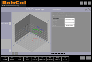
- RobCal software: checks the accuracy of the TCP measurement.
Data sheet and scope of delivery can be found on the Z1305 mobile TCP measuring device page, the comparison with the Z1022 and Z1502 in the overview of ZIS TCP measuring devices.
How to check the taught TCP
Check the taught TCP in two stages: first via the controller's quality value, then by reorienting about the TCP.
- Read the quality value: KUKA shows an error value in mm [2], ABB Mean Error and Max Error [5].
- Reorient: activate the tool, select the tool coordinate system, rotate only about the axes (ABB: motion mode Reorient). The tip must stay at the reference point [4] [5].
- Measure with the Z1305: connect the laptop with the RobCal software via Wi-Fi and rotate the robot about the TCP. RobCal calculates the TCP deviation in the 3 main planes.
- Compare with the process tolerance: in welding and cutting, an offset of less than 1 mm can already be too much. If the deviation exceeds the process tolerance, record the points again.
- Document: record tool number, date, method and quality value. RobCal outputs the measurement report as PDF and exports the measurement data as DXF.
Tip: Check every result by reorienting, even with a small quality value. The quality value only shows how well the approach points fit together, not whether the calculated point is at the right place on the tool.
Conclusion
For the TCP position, XYZ 4-Point on KUKA, Three Point on FANUC and TCP (default orient.) with 4 approach points on ABB are sufficient. If the tool works at an angle to the flange axis, also define the orientation: with ABC World or ABC 2-Point, Six Point or TCP&Z or TCP&Z,X. Clearly different orientations, an exactly hit point in space and checking by reorienting are decisive. If you look after robots of different brands or need measurement reports, use a measuring device such as the Z1305 as an electronic tip.
Frequently asked questions
Why is XYZ 4-Point not available on my palletizing robot?
KUKA excludes the XYZ 4-Point method for palletizing robots. On four-axis palletizing robots, enter the tool data numerically, for example from CAD or an external measurement [1].
What do UNINIT, RECORDED and USED mean in the FANUC Tool Frame?
UNINIT marks a point not yet recorded, RECORDED a recorded one. When all points of the selected method are recorded, USED is shown and the Tool Frame is calculated [4].
Can I reuse the approach points on ABB later?
Yes: before confirming, save the points to a file in the Positions menu with Save. Reset All discards all points so you can start again [5].
Why does the TCP differ when I teach it at another place in the workspace?
When teaching, the robot itself serves as the measuring machine; for large robots, ABB states differences of up to several millimetres between different areas of the workspace. According to ABB, follow-up measurements close to the previous one improve repeatability [5].
Do I have to reteach the programs after a tool change?
Usually not, if you teach the TCP of the new tool; FANUC America describes this as the way to keep existing programs accurate [3]. On KUKA, XYZ Reference determines the TCP of a new tool via an already measured one [1].
Can I define the TCP without a reference tip?
Yes: enter externally measured values directly, on KUKA via numeric input, on FANUC via Direct Entry [1] [4]. Alternatively, a measuring device such as the ZIS Z1305 replaces the tip and indicates by LED when the measuring position is reached.
Sources
- KUKA System Software 8.3 – Operating and Programming Instructions for System Integrators, KSS 8.3 SI V3 of 27 May 2014, ch. 5.10.2 Calibrating the tool (available to customers via KUKA Xpert), KUKA Roboter GmbH, accessed 27 Oct 2026
- J. Malott: Calibrate a New Tool (KUKA, XYZ 4 Point), as of 11 Feb 2025, School of Architecture, The University of Texas at Austin, accessed 27 Oct 2026
- FANUC User Tool Setup Tips, Tech Transfer of 1 Jun 2020, FANUC America Corporation, accessed 27 Oct 2026
- O. I. Cirilo-Piñón, J. E. Mastache-Mastache, R. López-Ramírez, J. Namigtle-Jiménez: Programming of industrial robot Fanuc LR Mate 200iD, 2022, ch. 2.5 (Tool Frame), ECORFAN, accessed 27 Oct 2026
- Operating manual – IRC5 with FlexPendant, RobotWare 6.08, 3HAC050941-001 Revision G (2018), ch. 5.5.4 Defining the tool frame (available to customers via ABB Library), ABB, accessed 27 Oct 2026